Description
Part-turn IP68 Electric Actuator Overview
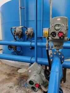
The part-turn ip68 electric actuator BJ/BJM80-IIC series from Bonray integrates seamlessly into new or existing valve assemblies. Our factory designed this actuator to eliminate common field frustrations: complex wiring, hazardous cover openings, and frequent mechanical failures. You can install it on any quarter-turn valve—butterfly, ball, plug, or damper—using standard ISO5211 mounting pads or optional crank-arm brackets (JZJ series). We ship each unit with a full set of terminal labels and a quick-start guide. Because we build every actuator in our ISO-certified facility, you receive consistent quality: each unit undergoes a 48-hour burn-in and full torque calibration.
The part-turn ip68 electric actuator supports both IP68 waterproof and explosion-proof enclosures, so you can deploy it indoors, outdoors, in pits, or in hazardous zones (1/2 for gas, 21/22 for dust). This overview walks you through the installation process, from mechanical mounting to electrical termination, using active voice instructions directly from our factory field engineers.
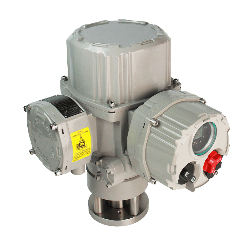
Can I wire the part-turn ip68 electric actuator without removing the terminal cover completely?
Yes. The double-seal terminal box has an outer cover and an inner seal plate. You remove the outer cover, then access the terminals through the seal plate openings. This inner seal remains compressed, keeping moisture away from the main electronics. Our factory recommends using flexible cables (0.8–2.5 mm²) and ferrules for vibration resistance.
Features
From an installer’s perspective, the part-turn ip68 electric actuator offers these practical features:
Tool-Free Parameter Adjustment
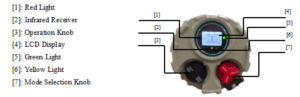
The magnetic rotary knob and infrared setter allow you to configure limits, torque, control modes, and relay assignments without any screwdriver. Just turn the knob to scroll through menus; press to select. The LCD displays real-time feedback. Our factory pre-sets basic limits to 0° and 90°, but you can fine-tune them in minutes.
Self-Diagnostic Power-Up Sequence
Upon applying power, the actuator runs a self-check: it verifies encoder communication, torque sensor integrity, memory checksum, and phase presence. Any fault appears on the screen. This saves you from troubleshooting dead circuits. Our factory test logs each unit’s power-up sequence before packing.
Cable Entry Versatility
The terminal box includes two M20 and one M27 threaded holes. You can install standard plastic or metal glands, or use conduit adapters. For crowded cabinets, our factory offers a plug-in terminal block (CB1 option) that lets you pre-wire a removable connector.
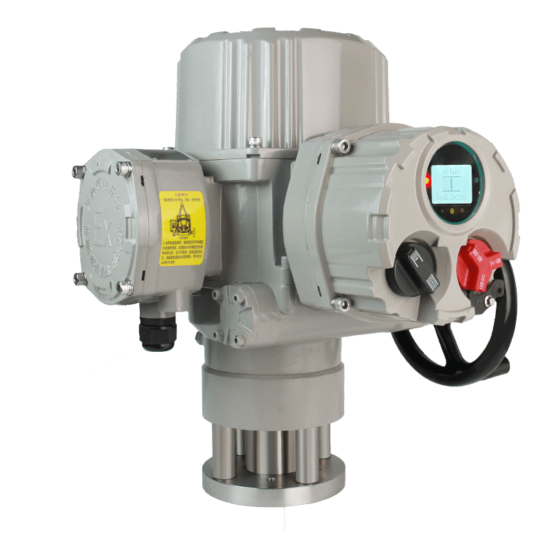
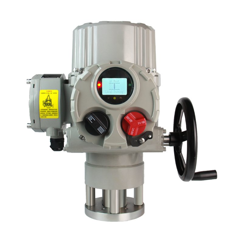
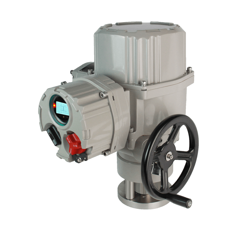
Visual Position Indication
Even without power, the large mechanical pointer on the output flange shows valve position. Additionally, the LCD shows a bar graph and percentage. Three high-brightness LEDs (green for open, red for closed, yellow for mid-travel) are visible from 10 meters away.
Emergency Manual Override with Lockout
The handwheel includes a provision for a padlock. You can lock the actuator in any manual position to prevent unauthorized electrical operation during maintenance. Our factory can also supply a chainwheel adapter for overhead valves.
Field-Adjustable Travel Stops
Mechanical stops (optional on some models) allow you to limit the travel range independently of the electronic limits. This provides a backup safety stop if the control circuit fails. Our factory can install these on request (specify “mechanical stop” in order).
Data Logging Capability
The part-turn ip68 electric actuator stores the last 100 events (torque peaks, limit trips, power failures, ESD activations). You can view them on the LCD or download via the optional Bluetooth dongle. This helps troubleshoot intermittent valve sticking.
Data Sheet
| BJ80-IIC | Output speed (rpm) | Rated torque (N.m) | Motor power (W) | Rated current (A) | Locked-rotor current (A) | Number of manual turns (n) | Weight (kg) |
| 24Vdc | 0.5 | 800 | 150 | 13 | 33 | 20.25 | 30 |
| 1 | 400 | ||||||
| 2 | 200 | ||||||
| Single phase | 0.5 | 800 | 140 | 1.92 | 4 | 20.25 | 30 |
| 1 | 400 | ||||||
| 2 | 200 | ||||||
| Three phase | 0.5 | 800 | 120 | 1.28 | 2.57 | 20.25 | 30 |
| 1 | 400 | ||||||
| 2 | 200 |
Specifications
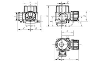
For mechanical installation, these dimensional and environmental specs matter most.
| Installation Parameter | Value |
| Flange standards | ISO5211:2017 (GB/T12223-2023). Also non-standard upon request. |
| Drive sleeve | Splined bore; can be machined to any keyway/diameter (specify when ordering). |
| Mounting orientation | Any angle (the sealed housing works upright, inverted, or side). |
| Manual override turns per 90° | 14 (BJ05-10) to 36 (BJ300). |
| Handwheel torque | ≤200 N (force on rim). Our factory uses ergonomic rim diameter of 200-300 mm. |
| Cable gland threads | 2x M20x1.5 (for 9-14 mm cable), 1x M27x2 (for 13-18 mm cable). |
| Terminal wire size | 0.8 – 2.5 mm² (stranded or solid). Use ferrules for stranded. |
| Ground terminals | Internal and external grounding points (brass stud). |
| Operating temperature | -30°C to +70°C. Optional -40°C to +70°C (LT40 option). |
| Storage temperature | -40°C to +85°C (our factory tests to -50°C for cold climate orders). |
| Humidity | 0-95% non-condensing (IP68 rating ensures submersion). |
| Vibration resistance | 5g, 10-200Hz (tested on our factory shaker table). |
| Weight | See Table 4 in manual (range 14-65 kg). |
All installation hardware (bolts, washers, O-rings) ships with the actuator. Our factory also provides a downloadable CAD model (STEP file) for interference checks.