Description
Part-turn Explosion-proof Actuator Overview
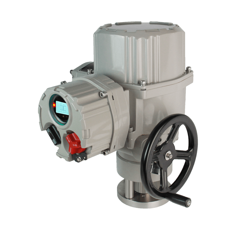
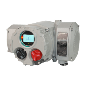
When you select a part-turn explosion-proof actuator for your plant, you need a device that installs quickly, wires without confusion, and survives decades of service. The BJ10-IIC Series from Bonray (a factory known for robust mechanical design and non-intrusive electronics) meets these demands directly. This part-turn explosion-proof actuator integrates a patented planetary gearbox that eliminates the hand/auto shift lever – a component that fails often on worm-gear actuators. Our factory builds each unit with dual IP68 seals, so you can mount it in a pit or outdoors without worry.
The part-turn explosion-proof actuator accepts universal control signals: dry contacts, 24Vdc, 220Vac, 4-20mA, and major fieldbuses. You configure all parameters – torque limits, control behavior, ESD logic – through a magnetic knob or infrared tool, without removing the electrical cover. The factory pre-lubricates each gearbox with high-grade grease, so you never need to open the unit for maintenance. With output torque from 50 N.m to 3000 N.m and speeds from 0.16 to 1 rpm, this actuator fits any quarter-turn valve from DN50 to DN1200.
Part-turn Explosion-proof Actuator Features
1. Tool-Free Commissioning
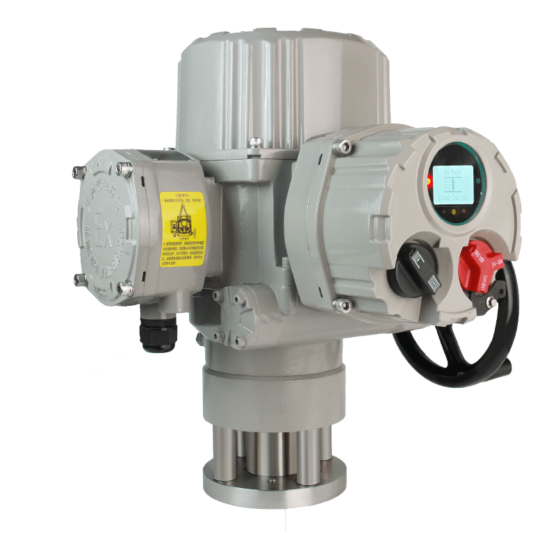
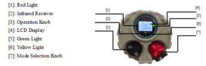
The factory programs the LCD to show real torque, position, and alarms in plain text.
You use the same local knobs to set open/close limits, torque trip values, and control deadband.
The non-intrusive design means you commission the part-turn explosion-proof actuator even in rain or dust storms.

IP68 Diving Test Chamber
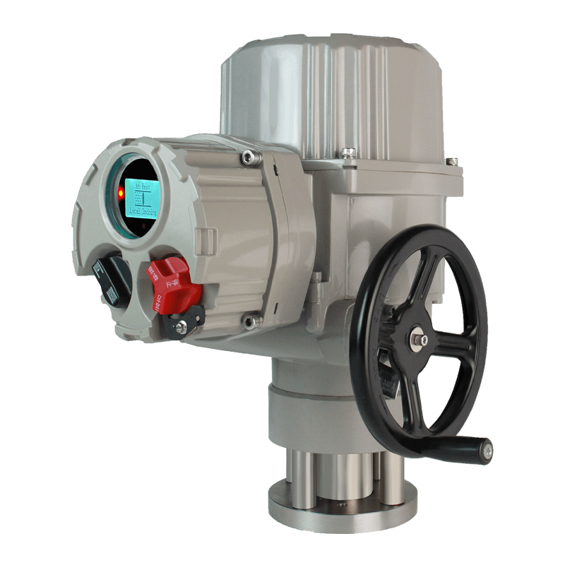
2. Dual Seal for Harsh Environments
Static joints use O-rings; dynamic joints use oil seals.
The terminal box has a second inner seal – you can wire the actuator without exposing internal electronics.
IP68 rating: submersible at 2 meters for 48 hours.
Flameproof version (Ex db IIC T4 Gb) suits Zone 1 and Zone 2 gas areas.
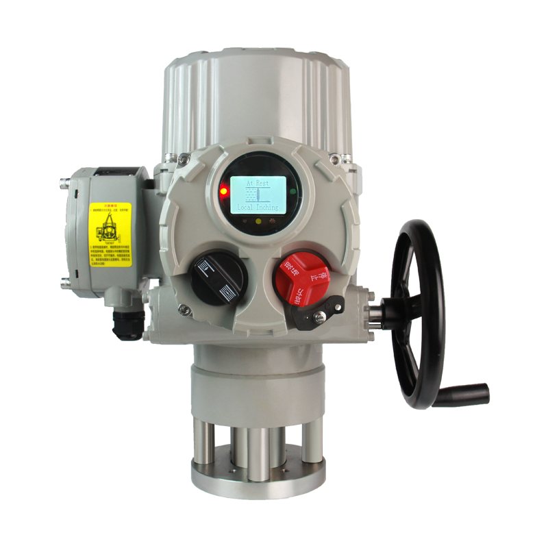
3. Absolute Torque Measurement
The factory’s proprietary sensor directly measures output torque, not motor current.
Non-contact design means no wear, no calibration drift.
You see the actual torque on the LCD and can set a torque trip to protect expensive valves.
4. Simplified Wiring
Terminal blocks accept 0.8-2.5mm² wires with a screwless pressure clamp.
Two main wiring diagrams: type 62x (bistable contacts) and type Q2x (monostable contacts).
The factory labels every terminal clearly: power (U,V,W), control (R-CLOSE, R-OPEN, R-HOLD), feedback (CPT+, CPT-), and analog setpoint (APC+, APC-).
5. Smart Phase Correction
The part-turn explosion-proof intelligent actuator detects the phase sequence of your 3-phase supply.
It internally selects the correct contactor – you never swap wires to change motor direction.
Phase loss protection stops the motor immediately, preventing burnouts.
6. Adjustable ESD Override
You configure ESD as active-high or active-low.
Choose whether ESD overrides a motor overheat condition or a local stop command.
ESD can force “close”, “open”, or “disable all actions”.
7. Two-Wire Control for Remote Locations
For long cable runs, use two-wire control: “signal opens valve, no-signal closes valve” or reverse.
This part-turn explosion-proof actuator saves wiring costs on pipelines and remote wellheads.
Model and Type
The factory produces three core variants of the part-turn explosion-proof actuator. Each variant shares the same mechanical housing, gearbox, and absolute sensors – only the control board and motor duty cycle differ.
BJ10-IIC On-Off (Standard Switch)
No analog control board. Accepts only digital signals (dry contacts or voltage).
60 starts/hour max. Simple open/close for gate valves, penstocks, and on/off ball valves.

Split-type Actuator Control Box
BJ10-IIC Intermittent Modulating
Adds a 4-20mA input board for position control.
Same duty as on-off type: 60 starts/hour. For process regulation where speed is not critical.
BJM10-IIC Frequent Modulating (High Cycle)
Solid-state relays eliminate contact wear.
Up to 1200 starts/hour (600 for single-phase). Duty cycle 50%.
Includes a higher-grade control chip for ±0.5% positioning accuracy.
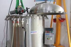
Split-Body Option (BJM-IICF)
The factory mounts the controller in a separate enclosure.
You place the actuator in a hot zone (up to 70°C+) or on a vibrating pump.
The controller sits in a cool, safe area up to 10 meters away (cable included).
Retains all features: absolute encoding, non-intrusive setup, bus communication.
Specifications
| Parameter | Value |
|---|---|
| Rated Torque Range | 50 N.m to 3000 N.m |
| Output Speed | 0.16, 0.3, 0.5, 1.0 rpm (other speeds upon factory request) |
| Max Stroke | 100° (adjustable ±5°) |
| Manual Override | Handwheel (direct drive, no clutch mechanism) |
| Handwheel Turns for 90° | 14 to 65 turns depending on model |
| Weight | 20 kg (BJ05) to 63.5 kg (BJ300) |
| Control Input Impedance | ≥100Ω for analog; dry contact wetting voltage 24Vdc |
| Analog Output Load | ≤750Ω |
| Relay Contact Rating | 5A at 250Vac or 30Vdc |
| Environmental | -30°C to +70°C; optional -40°C or -60°C |
| Housing Material | Die-cast aluminum with phosphate + coating |
| Fasteners | Stainless steel |
| Factory Calibration | Each unit runs on a test bench with torque verification before shipping |
What should I do if the LCD shows “Torque Trip” but the valve is not stuck?
The absolute torque sensor may have detected a transient spike. First, manually operate the handwheel to verify free movement. Then enter the menu and check the “Peak Torque Log”. If the peak is below your set trip point, reset the alarm. If it repeats, contact the factory – the sensor may need re-zeroing.